Controlling BLDC Motor for Vehicle with CTUCAN
This is to update on completion of Milestone 3 of the project which involved controlling a motor on the CAN network with CTUCAN device. We would need to have a motor contoller to interface with our CAN bus and control the motor.
The ODrive is a motor control board based on the STM32 microcontroller. It can be used with BLDC motors (brushless DC motors), over a CAN bus to set acceleration, braking, and other parameters for motor control systems.
Hardware for ODrive is available for sale on online shop: https://odriverobotics.com/shop
The entire firware and GUI software to interface with Odrive is available on GitHub: https://github.com/odriverobotics/ODrive/
Hardware Requirements
- A brushless motor.
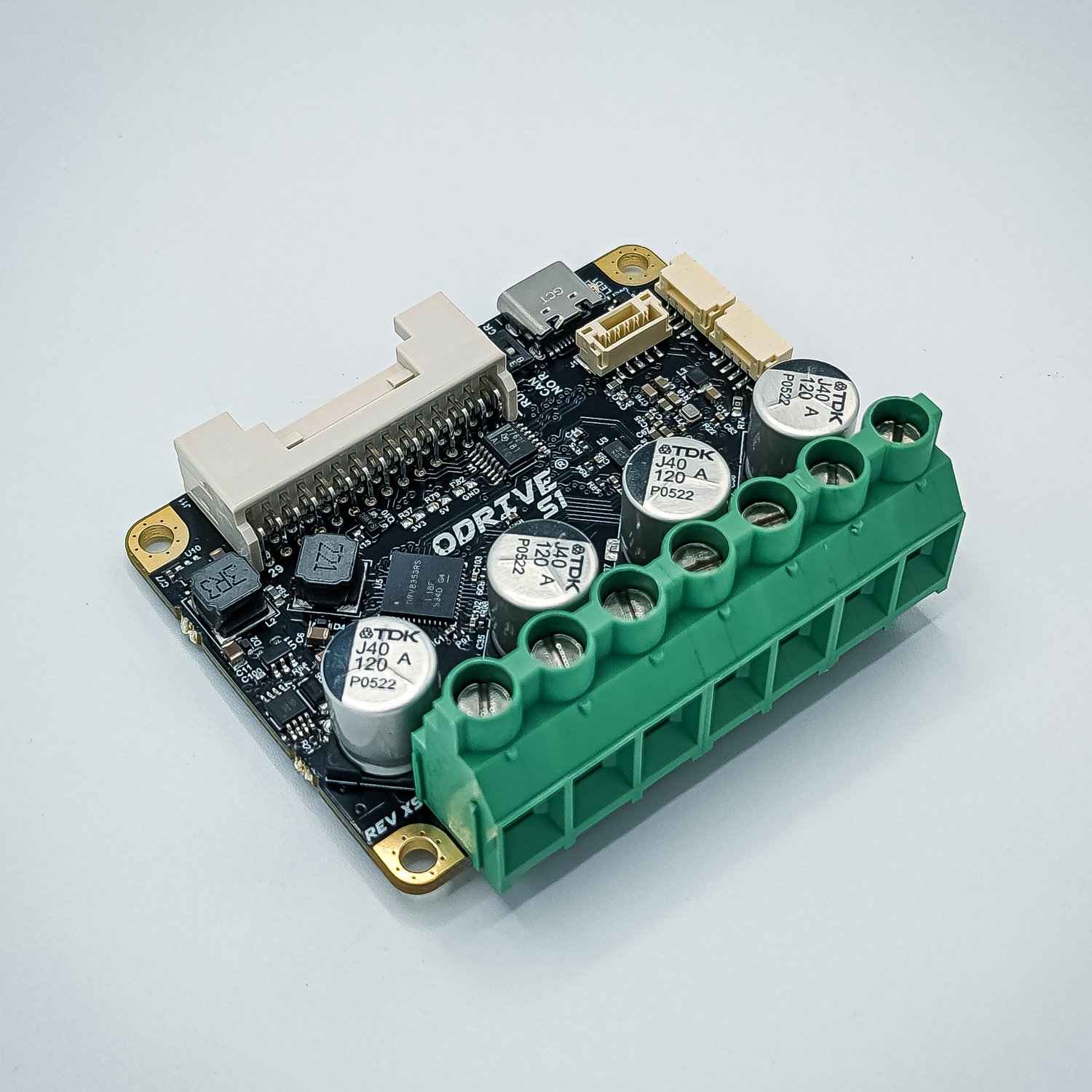
- Odrive S1
- FPGA device with CAN controller/transceiver
- A >12V power supply or battery.
Hardware Connections
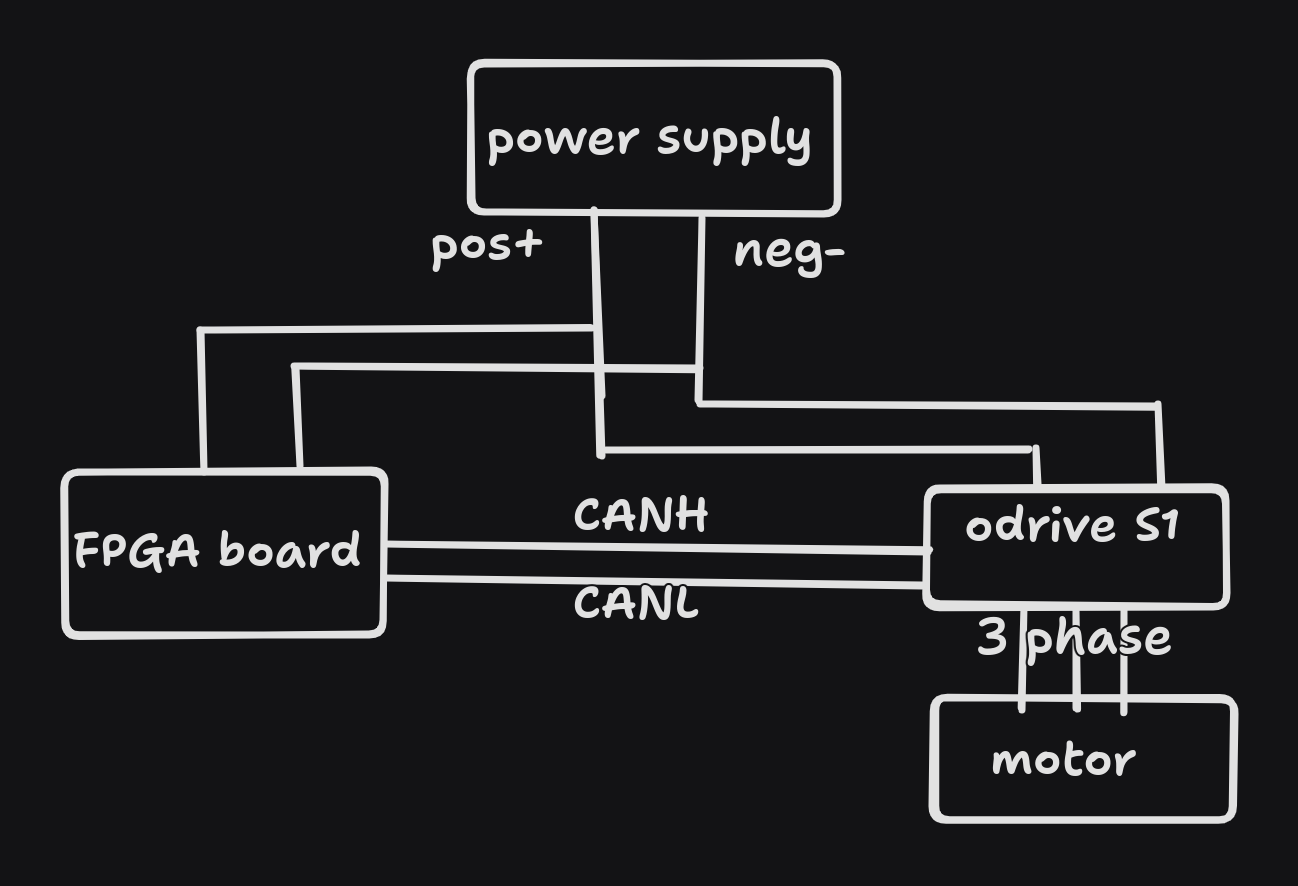
- Connect screw terminals representing the motor phases to A/B/C of Odrive S1 Power Pads.
- Connect the power supply cables to Odrive S1 solder pads that are labelled +/- and Arty A7 board
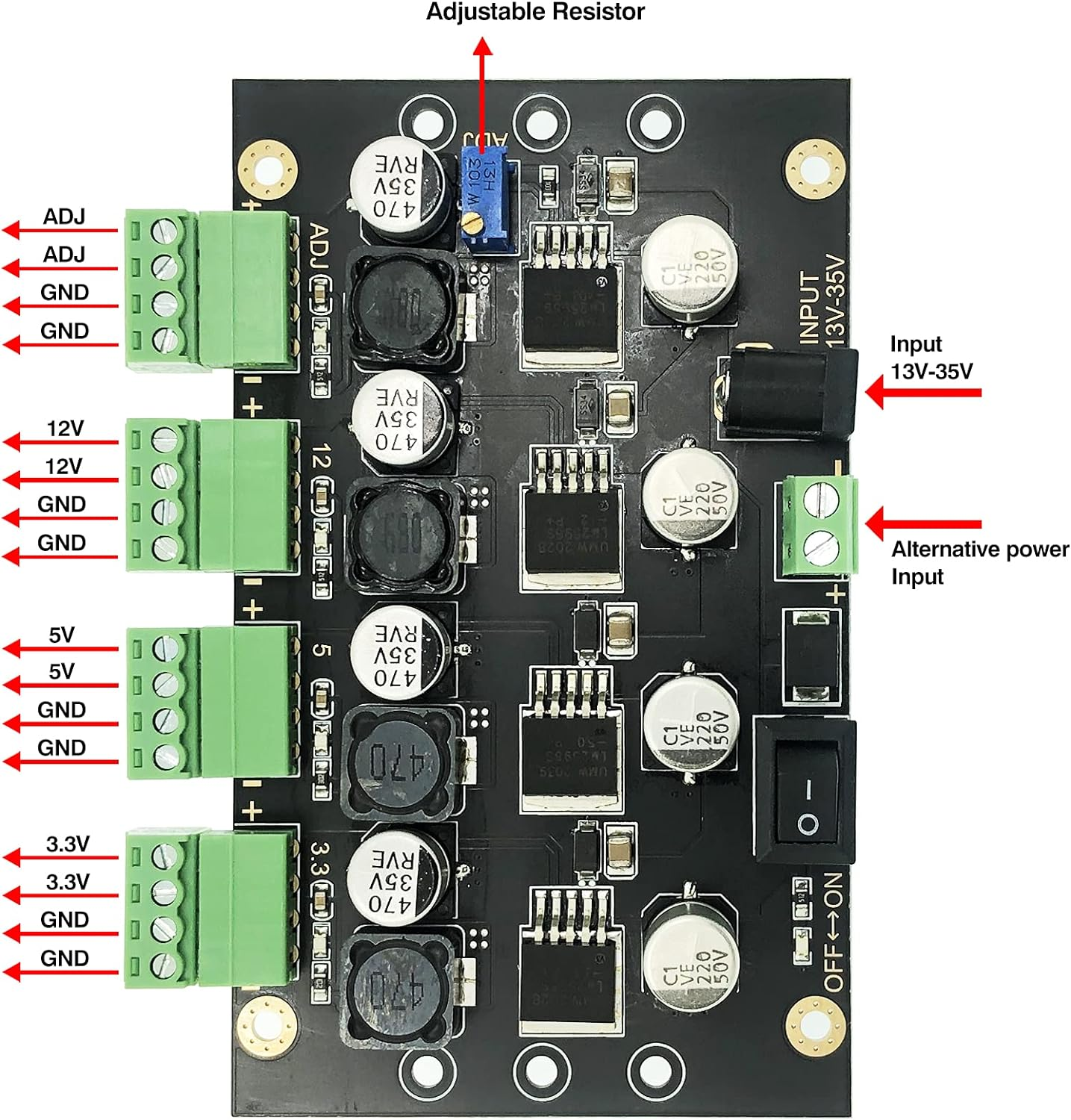
Since CAN bus is not isolated, use power supply to power both. To run Arty A7 board with same DC source, below accesories can be used :
- DC-DC convertor : https://amzn.eu/d/iUmVObb
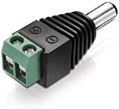
- DC Hollow Connector : https://amzn.eu/d/gej5q8E
- Connect Odrive S1 with FPGA board over CAN bus.
- Connect motor to Odrive S1 via 3 phase wire.
Complete setup can be illustrated in below daigram
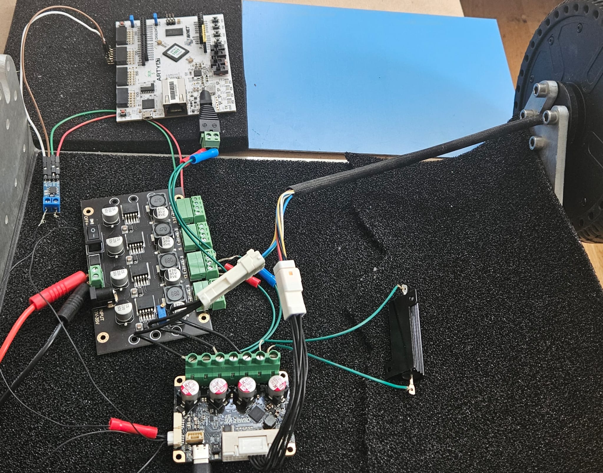
In reality, it resemebles like seen in below image:
Controlling Motor Controller with CAN bus
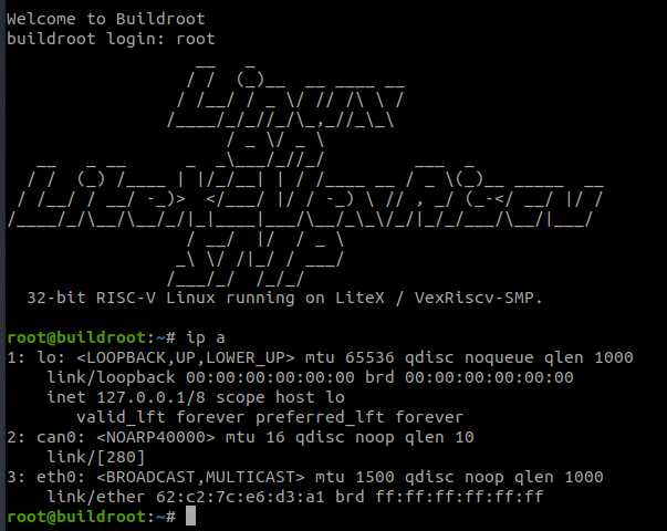
- Power up Arty board with CTUCAN driver enabled
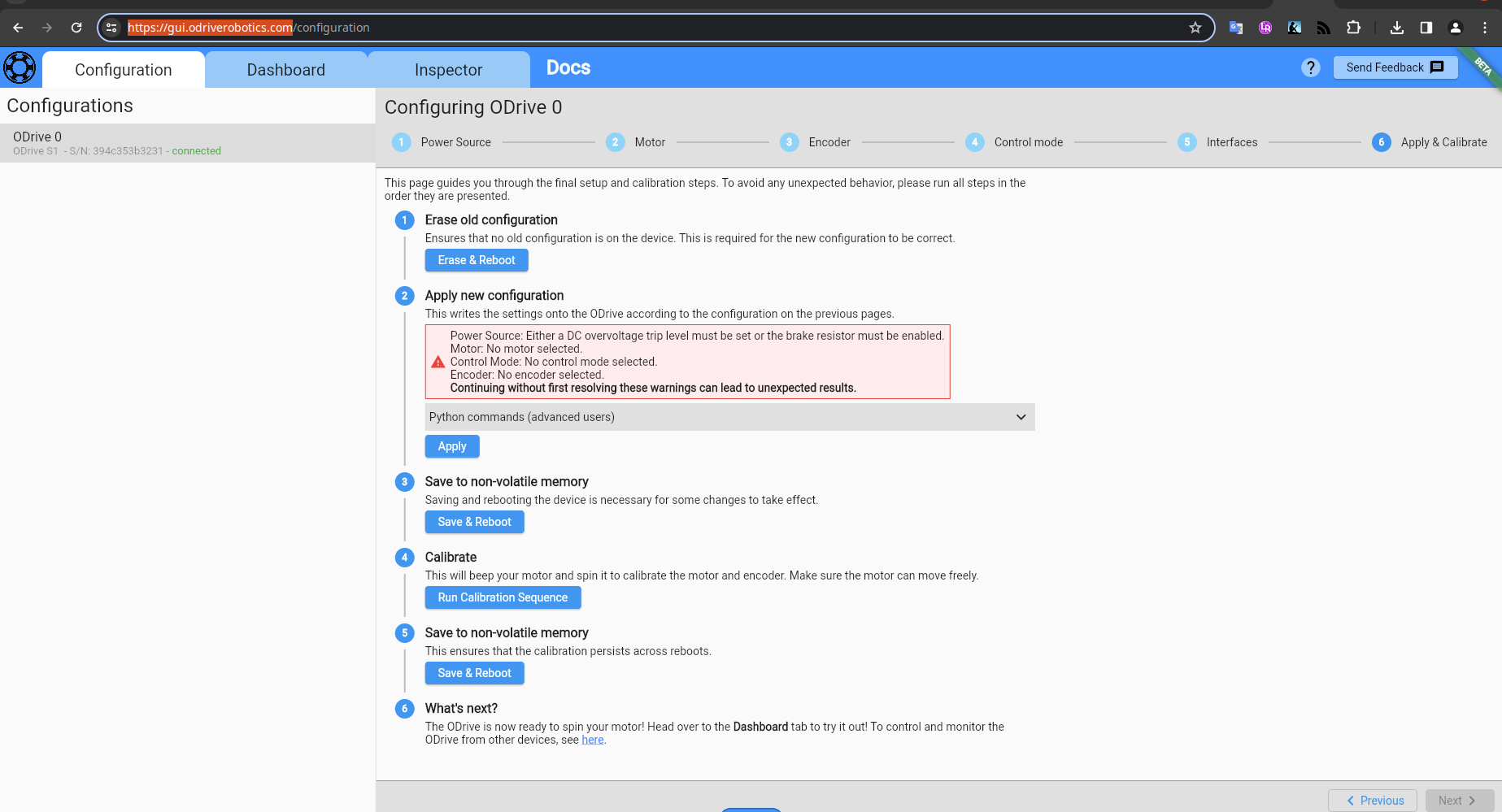
- Use GUI Wizard of Odrive to calibrate the motor.
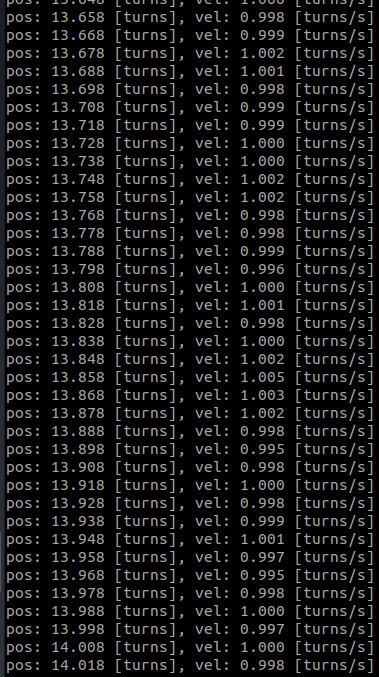
- Check if any data is recevied on CAN bus with candump
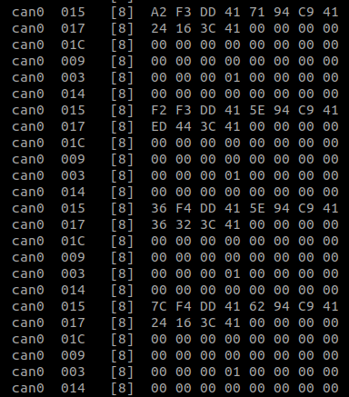
To make sense of this data we would use CAN Simple protocol provided by Odrive.
https://github.com/odriverobotics/ODriveResources/blob/master/examples/can_simple.py
Motor should start rotating with torque of 1 turns per second.